Frequency Divider and Counters
Introduction and Backgrounds
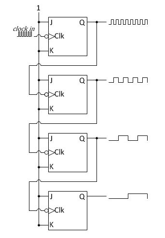
In order to obtain the required frequency for seconds, minute and hour from the 60Hz signal generated by the Schmitt Trigger, a divider circuitry must be used. The divider circuitry is essentially the same as a binary counter. In an asynchronous configuration, the flip-flop receives the clock input and the rest of the flip-flop receives output from the previous flip-flop as their clock input. Each proceeding flip-flop divides the frequency by two. Another way to achieve this is the synchronous configuration, which is slightly more complex but does not suffer from successive propagation delays.
Asynchronous Configuration
n-Bit counters
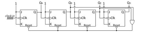
MOD-6 counter
In order to create dividers that divides other than a power of 2, the reset can be used in conjunction with a NAND gate. By connecting the high outputs in the binary number of the desired frequency to the NAND gate, the device will reset its flip-flops as soon as it reaches that frequency.
System Description
For this project 74LS90 and 74LS93 are used to create Mod-10 and Mod-6 counter respectively. When the input of Mod-10 is connected the by the output of Mod-6, the result is Mod-60.
3 Mod-60 will be used to divide the 60Hz clock down to 1 per hour. To do this, the output of the first Mod-60 is fed in the input clock of the second and the same for the third one as well. A special MOD-24 counter will be used to count the 24 hours in a day. This is accomplished using two 74LS90 by putting a AND from the output of 4 and the output of 2 into the reset of both chips. This means that the counter will clear once 4 is on hour0 and 2 is on the hour1 bits.
3 Mod-60 will be used to divide the 60Hz clock down to 1 per hour. To do this, the output of the first Mod-60 is fed in the input clock of the second and the same for the third one as well. A special MOD-24 counter will be used to count the 24 hours in a day. This is accomplished using two 74LS90 by putting a AND from the output of 4 and the output of 2 into the reset of both chips. This means that the counter will clear once 4 is on hour0 and 2 is on the hour1 bits.
Testing
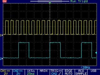
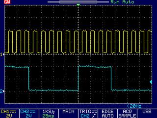
1. Test individual dividers under the oscilloscope with a know frequency, and see if it actually divides the frequency by the predicted amount.
2. Wire together the MOD-60 and the MOD-24, attach LED too the output of each sub device. count the number of flashes for each corresponding LED. Use a faster clock speed when testing Hour0 and Hour1 counters, the divide by 24 counters.
On and off does not occupy the same time due to duty cycle of a bout 25%.
Test 1: no waveform is detected on the oscilloscope
-checked datasheet.... output is wired correctly
Test 2: no waveform is detected on the oscilloscope
-checked datasheet.... MASTER sets and resets are floating high, now tied low
Test 3: Expected frequency division is visible on the oscilloscope
-checked datasheet.... output is wired correctly
Test 2: no waveform is detected on the oscilloscope
-checked datasheet.... MASTER sets and resets are floating high, now tied low
Test 3: Expected frequency division is visible on the oscilloscope
Mod6
|
Mod10
|
Test 4: Connected the third MOD10 and MOD6 output to buffers minute0 and minute1 respectively, and a LED is connected after the first MOD60 cluster. 7 segment displays 60 minutes and flashes on the seconds
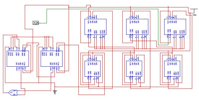
Counter Integration
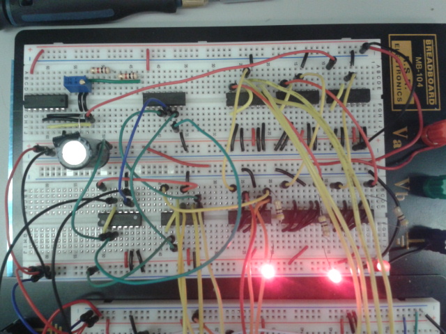
Frequency dividers with 60Hz clock
Problems Encountered
When we first wired the MOD6 and MOD10 counters, the master sets and reset are not wired. Since TTL chip have a floating high voltage and the sets and resets have a active high, the system did not function as intended. This could have been avoided by simulating the circuit in Multisim first and then implementing it on the proto-board.
conclusion
After a bit of struggle wiring the first Mod10 counter, the rest of the frequency divider went fairly smoothly, abet some ground and power issues.
The working minute and hour counts on the 7 segments shows that the frequency dividers are working as intended.
For future endeavors, I recommend simulating circuit on Multisim first. This will save lots of time if something goes wrong during wiring stage.
The working minute and hour counts on the 7 segments shows that the frequency dividers are working as intended.
For future endeavors, I recommend simulating circuit on Multisim first. This will save lots of time if something goes wrong during wiring stage.
