Status Report - GREEN
60hz clock
Introduction & Background
The HD74LS14 is a Hex Schmitt Trigger inverter. What a Schmitt trigger is is a circuit that contains a loop gain greater than 1 and has a positive feedback. The output of this trigger retains its value until a significant change occurs to the input. This chip will be used in the project to provide the 60Hz clock.
In order to produce the desired 60Hz square wave signal, the inverter chip was used in the oscillator in astable mode.
System description
Astable mode
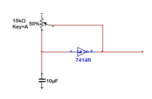
In the configuration shown to the left, the Schmitt oscillator produces a square waveform out of pin 4 on the inverter chip.
The formula used in order to calculate the required resistance required to achieve the desired 60Hz frequency is,
f = 0.8/(R1*C1)
Using the frequency (60Hz), the capacitance which will be 10uF, we can calculate the resistance. When rearranging the formula R1 = 0.8/(f*C1) so therefore the required resistance is 1.33kOhms.
Instead of using a resistance of 1.33kOhms, a 5kOhm potentiometer was used in order to ensure that the exact resistance can be achieved to produce the 60Hz frequency.
Circuit Diagram & Circuit on Breadboard
|
|
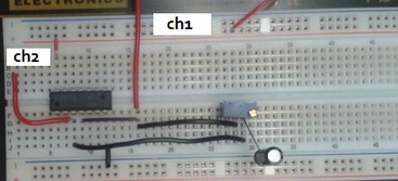
Shown above is the circuit diagram for the HD74LS14 inverter chip and a picture of the circuit on the breadboard.
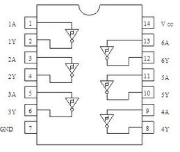
The pins being used in the circuit are as follows;
3. Input signal
4. Output signal
7. Ground
14. Supply Voltage
The pins being used in the circuit are as follows;
3. Input signal
4. Output signal
7. Ground
14. Supply Voltage
Testing
When testing, channel 1 on the oscilloscope was used. The positive lead was connected to pin 4 (the output of the inverter chip) and the negative lead was connected to the ground.
Result
The result of testing the frequency when the potentiometer was set to 1.33kOhms was displayed as 57.5Hz on the oscilloscope.
Tuning
In order to get the frequency to display as 60Hz the potentiometer was adjusted. The resultant resistance was measured to be 1.25kOhms.
Oscilloscope screen captures
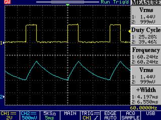
Figure 1: Initial waveforms and measurements
|
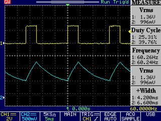
Figure 2: Waveforms and measurements after 24 hours
|
Conclusion
The Schmitt trigger inverter circuit was able to produce a 60Hz frequency initially and then successfully maintain its frequency over a 24 hour time period.
Resources
HD74LS14
5kOhm Potentiometer
10uF capacitor
Oscilloscope
Power Supply
Leads and wires
FreeView Software
The Schmitt trigger inverter circuit was able to produce a 60Hz frequency initially and then successfully maintain its frequency over a 24 hour time period.
Resources
HD74LS14
5kOhm Potentiometer
10uF capacitor
Oscilloscope
Power Supply
Leads and wires
FreeView Software
