Status Report - GREEN
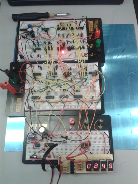
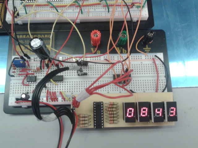
Integrated final circuit
Background theory : The last steps towards our working clock were mainly replacing the switches with chips that would give the numbers needed instead of the switch we had before. There was also some testing involved as we had to make quick fixes to ensure our clock was as accurate as it could be.
The chips feeding in the numbers are logic gates who divide the input frequency entered as input to a value given by how many times the initial frequency got divided by inside the chip's circuitry. For the minutes, we needed a MOD 6 and MOD 10 chips, so we could divide the incoming frequency signal of 60Hz down to 1Hz and then feed that value to the rest of the circuit. The hours were wired following the same logic, but since we don't need to reach the numbers 3 to 9 for the 2nd digit of the hour, (since a clock goes to 24 hours), we used different MOD chips for the appropriate division of the frequency. To have the MOD to stop counting the values up constantly, we integrated a separate AND chip, so that once the MOD values would reach 9, it will reset the value back to 0 by inputting a low value back into the counter.
System Description
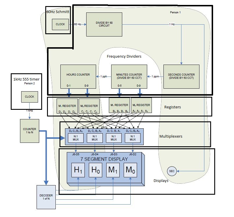
7-Segment display
The 7-segment display is the part of the circuit we chose to use to display the time. It was already made before the start of the project and was part of another project we've had in the past. The circuitry originates from the GAL chip soldered on its board, from which we use the logic to configure the other parts of our circuit to make sure they can work in between each other.
Multiplexers
The multiplexers are a series of chips which provide possible outputs taken from 8 possible inputs taken from another part of the circuitry. They feed in these values as the digits to be displayed by the 7-segment display board.
Registers
These are the logic gates that hold the binary values of the hours and minutes digits to be displayed on the 7-segment display. The logic gates used for this logic manipulation were 74LS174 Hex D Flip-Flop TTLs.
MOD counters
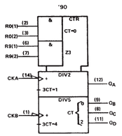
The MOD chips were used to get a clock frequency as input and then being able to take that frequency to feed an input into the registers. The logic used inside include dividing circuitry as shown in the picture above.
The chips feeding in the numbers are logic gates who divide the input frequency entered as input to a value given by how many times the initial frequency got divided by inside the chip's circuitry. For the minutes, we needed a MOD 6 and MOD 10 chips, so we could divide the incoming frequency signal of 60Hz down to 1Hz and then feed that value to the rest of the circuit. The hours were wired following the same logic, but since we don't need to reach the numbers 3 to 9 for the 2nd digit of the hour, (since a clock goes to 24 hours), we used different MOD chips for the appropriate division of the frequency. To have the MOD to stop counting the values up constantly, we integrated a separate AND chip, so that once the MOD values would reach 9, it will reset the value back to 0 by inputting a low value back into the counter.
System Description
7-Segment display
The 7-segment display is the part of the circuit we chose to use to display the time. It was already made before the start of the project and was part of another project we've had in the past. The circuitry originates from the GAL chip soldered on its board, from which we use the logic to configure the other parts of our circuit to make sure they can work in between each other.
Multiplexers
The multiplexers are a series of chips which provide possible outputs taken from 8 possible inputs taken from another part of the circuitry. They feed in these values as the digits to be displayed by the 7-segment display board.
Registers
These are the logic gates that hold the binary values of the hours and minutes digits to be displayed on the 7-segment display. The logic gates used for this logic manipulation were 74LS174 Hex D Flip-Flop TTLs.
MOD counters
The MOD chips were used to get a clock frequency as input and then being able to take that frequency to feed an input into the registers. The logic used inside include dividing circuitry as shown in the picture above.
Complete Schematic
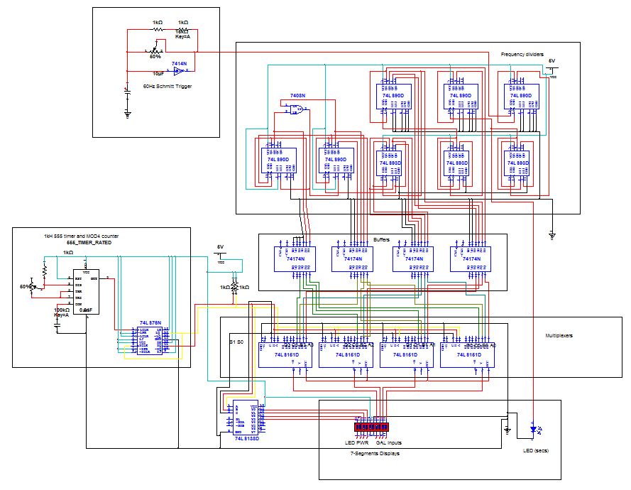
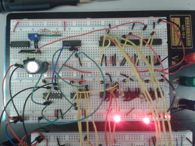
wiring
Overview
Display and 1kHz clock
|
Frequency dividers and 60Hz clock
|
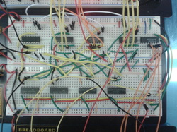
Registers and multiplexers
|
Testing PLan
Functionality test
Accuracy test
- Fast forward using function generator to check clock functionality.
Accuracy test
- Synchronize the 24 hours digital clock with manufactured clock (the one above the white board).
- Check difference after duration (12 hours, 24 hours)
Results
Clock functions as expected, Minute0 resets at 10, plus one to minute1, which reset at 6, then plus one to hour0.
hour0 resets at 10, plus one to Hour1, then resets at hour1 = 2 && hour0 =4
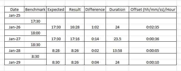
Accuracy results
Clock functions as expected, Minute0 resets at 10, plus one to minute1, which reset at 6, then plus one to hour0.
hour0 resets at 10, plus one to Hour1, then resets at hour1 = 2 && hour0 =4
Accuracy results
Problems encountered
Most of the problems encountered implementing the counters are wiring issues.
Its always good to have the datasheet of the chip(s) that you are wiring right in front of you for reference. NEVER assume Vcc or GND pin's location, well, never assuming any pin unless you are 100% sure. Even then, it never hurts to double check with the datasheet before connecting to power.
Another issue encountered was far more severe. The 60Hz clock from the schmitt trigger jumps between 58.98Hz to 60.24HZ
This was the reason that cause that 1:02 hour lag during the first accuracy test. To steady the frequency, I added two 1kOhm resistor in parallel with the potentiometer that was in place of the circuit before. This allow me finer control of the total resistance.
Overall, the digital clock is a success, have to meet the requirement of within 5 minutes of error after a duration of 24 hours.
Conclusion
Each sub-system worked together as expected and the digital clock is completed within the requirements.
There are several things that could be changed to make this project better in terms of easier implementation and more accurate meeting:
There are several things that could be changed to make this project better in terms of easier implementation and more accurate meeting:
- Try different capacitor <--> resistor combinations for obtaining the 60Hz frequency from the Schmitt trigger, bigger capacitor will give a steadier frequency.
- Try different resistor <--> potentiometer combinations. Putting them in parallel or in series can allow finer tuning or the overall resistance.
- Keep a consistent colour coding with every subsystem. Easier wiring, more intuitive and easier debugging.
- Plan out a proto-board layout. Keep it (the physical locations of the chips) consistent with the block diagram.
- Use a low pass filter to minimize disturbance going in to the 60Hz clock.
- Record debugging procedures in log book. You never know when the same problem might occur again.
- Isolate source of error. Test individual sub-systems and their sub-parts BEFORE integrating it into the main circuit. If the the whole system does not operate as expected, disconnect sub-system individually to test their functionalities.
- Don't be afraid to write down what went wrong or what didn't work. It helps you keep track of what didn't work and what did.
Completed on January 31st, 2013
